Iranian Classification Society Rules

< Previous | Contents | Next >
Annex 2-6 Guidance for liquid penetrant inspection and repair of defects of copper alloy propeller castings
1. Applications
This requirement applies to the liquid penetrant inspection and repair of defects of propeller castings. Repair method for propeller differing from those specified in this Guidance are to comply with the discretion of the Society.
2. The liquid penetrant inspection
(1) Area of test (Severity zones)
(a) In order to relate the degree of inspection to the criticality of defects in propeller blades and to help reduce the risk of failure by fatigue cracking after repair, propeller blades are divided into the three zones designated A, B and C as shown in Fig 1 and Fig 2
(b) The severity zones "A" are to be subjected to a dye penetrant inspection in the presence of the Surveyor. In zones "B" and "C" the dye penetrant inspection is to be performed by the manufacturer and may be witnessed by the Surveyor upon his request.
(c) If repairs have been made either by grinding or by welding the repaired areas are addition- ally to be subjected to the dye penetrant inspection independent of their location and/or se- verity zone.
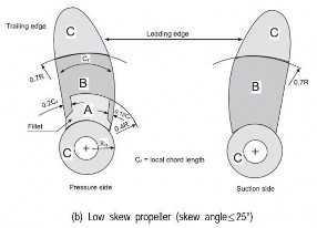
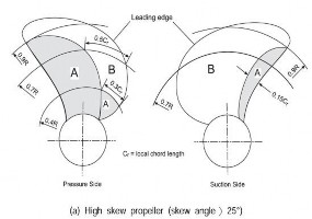
* The definition of skew angle comply with the requirements in the Pt 5, Ch 3, 303. of the Guidances (Notes)
1. R : The radius of the propeller, ![]() : The cord length at any radius
: The cord length at any radius
2. The boss area of an integrally cast propeller is regarded as Zone C.
3. Where stress distribution on propeller blade surface is estimated in detail, the non-destructive in- spection zones different from those shown in this figure may be applied subject to this Society's approval.
Fig 1 Zones for Non-destructive Inspection of Propeller Castings
![]()
Guidance Relating to the Rules for the Classification of Steel Ships 2015 73
![]()
Fig 2 Zones for Non-destructive Inspection on the Root Area of the Controllable Pitch or Build up Propeller Blades and Controllable Pitch Propeller Boss
(2) Methods of testing
(a) The methods of testing are to conform to the standard of K S B 0816 or equivalent.
(b) In the dye penetrant inspection an indication is the presence penetrant liquid from the material discontinuities appearing at
veloper has been applied.
(c) Where indications of defects appear, the type of defects and
of detectable bleed-out of the least 10 minutes after the de-
the size of the indications are
to be recorded in detail. These records are to be presented to the Surveyor. For reference, the true size of the defects are also to be confirmed.
(3) Types of defects
The defects detected by the liquid penetrant test are divided into following types of (A) to (D).
(A) Cracks : the defects regarded as a crack.
(B) Circular defects : the defects other than crack, in which the length is less than 3 times the width.
(C) Linear defects : the defects other than crack, in which the length is equal to or greater than
3 times the width.
(D) Aligned defects : Aligned defects consisting of two or more linear or circular defects which are almost aligned and the spacings between them do not exceed 2 mm. The length of an aligned defect is to be equal to the sum of the lengths of a1l individual defects and all
spacings between them.
(4) Acceptance criteria
(A) Where cracks or other defects which do not meet the acceptance criteria given in Table 1 are detected by the penetrant test, the defects are to be repaired in accordance with the re- quirements in 3.
![]()
74 Guidance Relating to the Rules for the Classification of Steel Ships 2015
![]()
Table 1 Acceptance Criteria
Are of test | Type of Defect (excluding crack) | Acceptance Criteria | ||
Max. total number of all defects(I) | defects of same type | |||
Max. number of each type(II) | Max. size for each indication(III) (mm) | |||
Zone A | Circular | 7 | 5 | 4 |
Linear | 2 | 3 | ||
Aligned | 2 | 3 | ||
Zone B | Circular | 14 | 10 | 6 |
Linear | 4 | 6 | ||
Aligned | 4 | 6 | ||
Zone C | Circular | 20 | 14 | 8 |
Linear | 6 | 6 | ||
Aligned | 6 | 6 | ||
(Notes) (1) The defects are to be repaired when they do not meet one or more criteria of (I) through (III) in this table. (2) The counting of the number of defects is to be conducted at the most unfavourable location rela- tive to the indication being evaluated. The area of a reference zone is to be 100 (3) Singular circular indications less than 2 mm for zone A and less than 3 mm for other zones may be disregarded. (4) Where only circular defects were detected, all defects(I) are to be repaired for the judgement. | ||||
(B) Areas which are prepared for welding are independent of their location always to be as- sessed according to zone A. The same applies to the welded areas after being finished ma- chined and/or grinded.
(C) Indications exceeding the acceptance standard of Table 1, cracks, shrinkage cavities, sand, slag and other non-metallic inclusions, blow holes and other discontinuities which may im-
pair the safe service of the propeller are defined as defects and must be repaired in accord-
ance with the requirements specified in 3 below.
3. Repair of defects
(1) Repair procedures
(A) In general, the repairs are to be carried out by mechanical means, e. g. by grinding, chip- ping or milling. After milling or chipping, grinding is to be applied for such defects.
(B) The contour of the ground depression is as smooth as possible in order to avoid stress con- centrations or to minimize cavitation corrosion.
(2) Repair of defects in zone A
(a) In zone A of Fig 1 and Fig 2, repair welding will generally not be allowed unless spe- cially approved by the Society.
(b)
Grinding may be carried out to an extent which maintains the blade thickness of the ap-
proved drawing.
(c) The possible repair of defects which are deeper than those referred to
sidered by the Society.
(3) Repair of defects in zone B
(a) In zone B of Fig 1 and Fig 2, defects that are not deeper than dB =
above is to be con-
(t/40) mm (t = min.
local thickness in mm according to the Rules) or 2 mm (whichever is
local thickness according to the Rules should be removed by grinding.
greatest) below
min.
(b)
Those defects that are deeper than allowable for removal by grinding welding.
may be repaired by
(c) Where the propellers in zone B in accordance with the requirements specified in previous
(b) are repaired by welding, the limits of the repair welding are to be as shown in Table 2.
![]()
Guidance Relating to the Rules for the Classification of Steel Ships 2015 75
![]()
![]()
![]()
![]()
Pressure side | Suction side | ||||
Each area of repair welding(1) | 75 | or 0.006 S whichever is larger | 150 | or 0.01 S whichever is larger | |
Total area of repair welding | 200 or 0.02 S whichever is larger | ||||
Depth of welding( ) | 0.1 basically | 0.15 basically | |||
Notes: (1) Welding of areas less than 5 cm2 is to be avoided. ∙ = Diameter of the propeller (cm) = Number of propeller blade = Developed area ratio (3) t is the thickness of the blade at the portion of repair welding.(cm) | |||||
Table 2 Limits of Repair Welding
(2)(3)
![]()
![]()
![]()
![]()
![]()
(4) Repair of defects in zone C
In zone C of Fig 1 and Fig 2, repair welds are generally permitted.
4. Repair Welding
Repair welding which permitted in accordance with the requirements in 3 (3) and comply with the following;
(1) General
(4) above is to
(a) Companies wishing to carry out welding work on propellers must have at their disposal the necessary workshops, lifting gear, welding equipment, preheating and, where necessary, an- nealing facilities, testing devices.
(b) All welding work is to be carried out preferably in the shop free from draughts and influ- ence of the weather.
(2) Welder
The welders are to have qualifications deemed appropriate by the Society.
(3) Edge preparation
(a) Defects to be repaired by welding are to be ground to sound material according to the re- quirements as given under para 3 (1). To ensure complete removal of the defects the ground areas are to be examined by dye penetrant methods in the presence of the Surveyor.
(b)
The edge preparation for repair welding after removing the defects is to be as shown in Fig
3 and 4.

Fig 3 Edge Preparation after Removing Defects
![]()
76 Guidance Relating to the Rules for the Classification of Steel Ships 2015
![]()

Fig 4 Edge Preparation for Repair Welding of Blade Edge
(4) Welding repair procedure
(a) Arc welding with coated electrodes and gas-shielded metal arc process (G M A W ) are gen- erally to be applied. Argon-shielded tungsten welding (G T A W ) should be used with care due to the higher specific heat input of this process.
(b) For material thickness less than 30 mm, gas welding may give a satisfactory weldment for
C U 1 and C U 2 materials.
(c) Recommended filler metals, pre-heating and stress relieving temperatures are listed in Table
3. However, the welding consumables are to be approved by the approval tests for welding procedure specified in (5).
(d) All propeller alloys are generally to be welded in down-hand (flat) position. Where this can-
not be done, gas-shielded metal arc welding should be carried out.
(e) The section to be welded is to be clean and dry. Flux-coated electrodes are to be dried be- fore welding according to the maker's instructions.
(f) Adequate pre-heating is to be carried out with care to avoid local overheating, c.f. Table 3.
(g) Slag, undercuts and other defects are to be removed before depositing the next run.
(h) To minimize distortion and the risk of cracking, interpass temperatures are to be kept low.
This is especially the case with C U 3 alloys.
![]()
![]()
![]()
![]()
![]()
Table 3 Recommended filler metals and heat treatments
Alloy type | Filler metal | Preheat temperature ( ) | Interpass temperature ( ) | Stress relief temperature ( ) | ||
CU 1 | Al-bronze(1) M n- bronze | 150 min | 300 | max | 350 | 500 |
CU 2 | Al-bronze N i-Mn-bronze | 150 min | 300 | max | 350 | 550 |
CU 3 | Al-bronze N i-Al-bronze(2) M n-Al-bronze | 50 min | 250 | max | 450 | 550 |
CU 4 | M n-Al-bronze | 100 min | 300 | max | 450 | 600 |
Notes: (1) Ni-A l-bronze and M n-Al-bronze are acceptable. (2) Stress relieving not required, if filler metal Ni-A l-bronze is used. | ||||||
![]()
![]()
(i) With the exception of alloy C U 3 (N i-A l-bronze) all weld repairs are to be stress relief heat treated, in order to avoid stress corrosion cracking. However, stress relief heat treatment of alloy C U 3 propeller castings may be required after major repairs in zone B (and specially approved welding in Zone A) or if a welding consumable susceptible to stress corrosion cracking is used. In such cases the propeller is to be either stress re- lief heat treated in the temperature 450 to 500°C or annealed in the temperature range 650- 800°C, depending on the extent of repair, c. f. Table 3.
![]()
Guidance Relating to the Rules for the Classification of Steel Ships 2015 77
![]()
(j) The soaking times for stress relief heat treatment of copper alloy propellers should be in accordance with Table 4. The heating and cooling is to be carried out slowly under controlled conditions. The cooling rate after any stress relieving heat treatment shall not exceed 50°C/h until the temperature of 200°C is reached.
Table 4 Soaking times for stress relief heat treatment of copper alloy propellers
Stress relief Temp. | Alloy grade C U1 and C U2 | Alloy grade CU3 and C U4 | ||
Hours per 25 mm thickness | Max. recommended total time hours | Hours per 25 mm thickness | Max. recommended total time hours | |
350 | 5 | 15 | - | - |
400 | 1 | 5 | - | - |
450 | 1/2 | 2 | 5 | 15 |
500 | 1/4 | 1 | 1 | 5 |
550 | 1/4 | 1/2 | 1/2 | 2 |
600 | - | - | 1/4 | 1 |
(5) Welding procedure qualification test
The manufacturer of propellers intending to carry out repair welding in zone B and zone C is
to pass the welding procedure qualification test as shown below. The qualification test is also to be in accordance with the requirements specified in Pt 2, Ch 2, Sec 4 of the Rules, in addi- tion to the following requirements:
(a) Tests for butt welding
(i) Test assembly
The test assembly as specified in Fig 5 is to be prepared by means of butt welding.
The edge preparation is, in principle, to be either the V shape or an appropriate shape and the bevel angle is to be not less than 60°.
(ii) Welding procedure
The welding procedures are to comply with the requirements in (5) above.
(iii) Visual inspection
The welded surface is to be regular and uniform and free from harmful defects such as cracks and undercuts.
(iv) Tensile test
Tensile tests are to be carried out using the two test specimens taken with Fig 5, and the values obtained are to be less than those given in
form of the test specimens are to comply with Fig 6.
in accordance
Table 5. The
![]()
Table 5 Tensile Test Requirements for Approval Test
Material | Tensile Strength ( ) |
C U 1 C U 2 C U 3 C U 4 | 370 min. 410 min. 500 min. 550 min. |
![]()
78 Guidance Relating to the Rules for the Classification of Steel Ships 2015
![]()
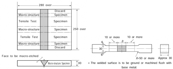
Fig 5 Test Assembly (Unit: mm) Fig 6 Size of Tensile Test Specimen (Unit : mm)
(b)
(v) Non-destructive inspection
Welded joint is to be tested for the whole length by liquid penetrant test, and is to show that there are no crack and other injurious defects.
(vi) Macro-structure inspection
Macro etched test specimen is to be prepared as shown in Fig 5. Pores greater than 3 mm and cracks not permitted.
Test of mold cavity welding
(i) Test piece and dimension of test piece
Test piece is to be of the material of same quality as the actual propeller. The di-
mensions of test piece are shown in Fig 7. The cavities are made as shown in the figure and then welding same as condition in the actual welding is carried out.
(ii) Sizes of cavities
Proper sizes permitting free operation of electrode.
(iii) Distribution of cavities
Distribution of cavities and distance of each cavity from the edge of test piece is to be such that these simulate the actual condition in the propeller to be welded.
(iv) Welding process
To be same as in the actual welding.
(v) Macro structure test
Macro structure test is to confirm that no defects such as crack exist in the cross sec-
tions of weld parts.

Fig 7 Test of mold cavity welding (Unit : mm)
(vi) Hardness test
Hardness test is to confirm that there is no unacceptable fluctuation in hardness between
the deposit metal, base metal and heat-affected zones. (vii)Non- destructive inspection
Welded joint is to be tested by liquid penetrant inspection or ultrasonic inspection and
is to free from any crack and other harmful defects.
![]()
Guidance Relating to the Rules for the Classification of Steel Ships 2015 79
![]()
(c) Additional tests
Where deemed necessary, additional tests may be requested by the Society.
5. Straightening
(1) Hot straightening
(a) Straightening of a bent propeller blade or pitch modification is to be carried out after heat- ing the bent region and approximately 500 mm wide zones on either side of it to the sug-
gested temperature range concentrated flames such
(b) Sufficient time is to be
given in Table 6. The heating is to be slow and uniform and the as oxy-acetylene and oxy-propane is not used.
allowed for the temperature to become fairly uniform through the
full thickness of the blade section. The temperature must be maintained within the range
given in Table 6 through the straightening operation.
![]()
![]()
![]()
![]()
![]()
Table 6 Temperature Range for hot Straightening
Material | CU 1 | C U 2 | CU 3 | C U 4 |
Temperature of hot straightening ( ) | 500 800 | 500 800 | 700 900 | 700 850 |
(c) A thermocouple instrument or temperature indicating crayons are to be used for measuring the temperature.
(d) The area heated is to be enclosed with asbestos or similar material to reduce the cooling speed after straightening.
(2) Cold straightening
Cold straightening is to be used for minor repairs of tips and edge only. Cold straightening on C U 1, C U 2 and C U 4 are to be followed by a stress relieving heat treatment(See Table 3 and Table 4)
(3) Application of load
For hot straightening, static loading and dynamic loading are to be used, but for cold straighten- ing, static loading is to be used only. ![]()
![]()
80 Guidance Relating to the Rules for the Classification of Steel Ships 2015
![]()